
Troubleshooting
Technical Tips
VSS Search
Please select your vehicle's year, make, and model below.
Installer Note: Rostra cruise control products purchased through eBay, Amazon, or Walmart are not eligible for technical support. Cruise control products must be purchased through an authorized distributor to receive technical support.

Cruise Control Notes
We do not recommend using any Rostra cruise control systems on motorcycle, ATV, or other non-automotive applications as we do not validate the operation of these units on these vehicles. Due to safety concerns surrounding these installations, Rostra representatives are unable to provide technical support on these applications.
Frequently Asked Questions
Located below this FAQ section, you will find installation manuals for each product Rostra manufacturers including aftermarket cruise controls, backup camera systems, ultrasonic parking assist systems, seat heaters, and automotive lumbar support.
To acquire both vehicle speed signal (VSS), brake wire, and tachometer wiring colors and locations, please use our VSS Search above. If you do not see your vehicle listed, please download Rostra forms Form #4428 (for vehicles built between 1996 and 2009) or Form #4429 (for vehicles built between 1986 and 1995).
The majority of Rostra-manufactured cruise controls systems are sold as complete kits. As well, Rostra manufactures universal cruise control units that often require the purchase of additional items to function with certain vehicles including vehicle speed signal (VSS) generators and control switches. To get a listing of exactly what parts will be necessary for your vehicle, please use the Vehicle Search menu at the top of the page or download our Cruise Control Quick Reference Guide. If you have questions about a customized cruise kit or other vehicle applications, feel free to call our Customer Service department at (407) 584-5724.
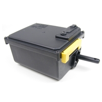
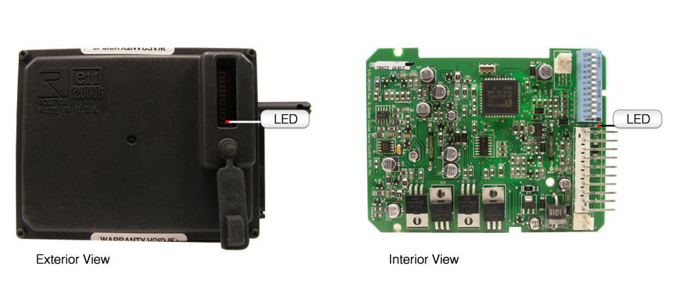
The LED is a surface-mount light on the circuit board to the left of switch number ONE of the programming switches.
The programming switches are located under the black rubber grommet on top of the cruise module. (See images below)
Gain is how the cruise control reacts to both road conditions and engine size. Always start at the factory setting which is Mid-Gain. If the vehicle surges while the cruise is engaged, you will need to adjust the gain setting. A fast surge, when the vehicle speeds up rapdily above the cruising speed, requires the gain to be lowered. Set the gain to Low or Extra-Low if needed. A slow surge, where the vehicle slows well below the cruising speed, requires the gain to be raised to High.
Engine/Setup Timer is how fast the cruise control retracts the cable once the cruise is set. Always start at Low. If the vehicle drops below the set cruising speed but then recovers, set to Medium. Set to High or Extra-High if still not acceptable.
RF steering wheel-mounted switches can be installed on several vehicles, but are not recommended for every vehicle. To find out if your vehicle has an RF switch available, check out our application guide.
Have no fear! Just because your vehicle is not listed in our application guide doesn't necessarily mean we don't offer a cruise control kit for it. Call our customer service department at (407) 584-5724 for specific application questions.
LED Tail Lights Note
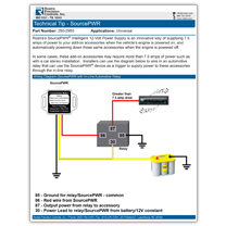
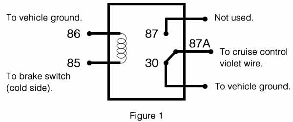
The use of LED tail lights requires a five-function automotive relay to bypass the brake system. LED tail lights do not let the violet wire (cold side of the brake switch) see ground through the brake lights, themselves. Wiring in a relay is as follows:
Click here to download a PDF version of this relay wiring diagram.
Note:
All settings are based on 1/8-inch slack in cruise control cable. More slack will cause the cruise control to surge or lose speed once set.
Product Installation Manuals
Installer Note: "XX" designation below used in place of speed limit setting (i.e., 250-9608-65)
- 250-9806-XX
- Form #5668
- 250-9808-XX
- Form #5688
- 250-9809-XX
- Form #5675
- 250-9810-XX
- Form #5687
- 250-9811-XX
- Form #5687
- 250-9812-XX
- Form #5677
- 250-9813-XX
- Form #5667
- 250-9817-XX
- Form #5691
- 250-9819-XX
- Form #4281106
- 250-9823-XX
- Form #5690
- 250-9824-XX
- Form #4281103
- 250-9829-XX
- Form #5692
- 250-9835-XX
- Form #5677
- 250-9836-XX
- Form #5693
- 250-9839-XX
- Form #5686
- 250-9842-XX
- Form #5697
- 250-9846-XX
- Form #5725
- 250-9848-XX
- Form #4281067
- 250-9850-XX
- Form #5722
- 250-9851-XX
- Form #4281110
- 250-9852-XX
- Form #4281112
- 250-9853-XX
- Form #4281112
- 250-9858-XX
- Form #5714
- 250-9861-XX
- Form #5715
- 250-9866-XX
- Form #5752
- 250-9867-XX
- Form #5756
- 250-9868-XX
- Form #4281044
Electronic Vehicle Speed-Limiter Two-Way Relay Wiring
- 250-9509-NS
- Form #5543
- Operator's Manual
- 250-9608-NS
- Form #5542
- Operator's Manual
- 250-9609-NS
- Form #5547
- Operator's Manual
- 250-9612-NS
- Form #5535
- Operator's Manual
- 250-9634-NS
- Form #5534
- Operator's Manual
- 250-9624-NS
- Form #4281118
- Operator's Manual
- 250-9635-NS
- Form #5531
- Operator's Manual
- 250-9636-NS
- Form #5541
- Operator's Manual
- 250-9646-NS
- Form #5278
- Operator's Manual
- 250-9647-NS
- Form #4281090
- Operator's Manual
- 250-9648-NS
- Form #4281065
- Operator's Manual
- 250-9651-NS
- Form #4281114
- Operator's Manual
- 250-9652-NS
- Form #4281113
- Operator's Manual
- 250-9661-NS
- Form #5717
- Operator's Manual
- 250-9668-NS
- Form #4281041
- Operator's Manual
- 250-1223
- Form #4565
- REV. G, 05-21-12
- Form #4428
- REV. L, 02-17-09
- Form #4429
- REV. A, 10-22-01
- 250-1729-TB
- Form #4731
- REV. A, 06-29-04
- 250-1731
- Form #5156
- REV. H, 09-06-11
- 250-1732
- Form #5164
- REV. A, 09-08-09
- 250-1753
- Form #4837
- REV. A, 06-29-04
- 250-1755
- Form #4838
- REV. A, 09-28-05
- 250-1766
- Form #4851
- REV. RTP, 08-17-04
- 250-1768
- Form #4856
- REV. B, 03-04-14
- Form #4903
- REV. B, 03-04-14
- 250-1771
- Form #4901
- REV. B, 03-04-14
- Form #4903
- REV. B, 03-04-14
- 250-1774
- Form #4193
- REV. C, 04-07-11
- Form #4904
- REV. D, 09-02-09
- 250-1775
- Form #4193
- REV. C, 04-07-11
- Form #4909
- REV. F, 06-10-10
- 250-1779
- Form #4914
- REV. C, 08-08-08
- 250-1799
- Form #5051
- REV. C, 08-31-11
- 250-1836
- Form #5156
- REV. J, 10-10-12
- Form #5188
- REV. F, 03-12-13
- Form #5350
- REV. RTP, 05-08-12
- Form #5367
- REV. A, 10-10-12
- Form #5368
- REV. A, 10-10-12
- Form #5369
- REV. A, 10-10-12
- Form #5370
- REV. A, 10-10-12
- 250-1840
- Form #5208
- REV. C, 05-16-12
- 250-1847
- Form #5219
- REV. C, 09-14-10
- Form #5661
- REV. A, 12-12-16
- 250-1848
- Form #5213
- REV. C, 04-07-11
- 250-1855
- Form #5221
- REV. H, 06-15-12
- 250-1856
- Form #5222
- REV. E, 09-30-10
- 250-1857
- Form #5225
- REV. B, 07-29-10
- 250-1858
- Form #5232
- REV. B, 09-14-10
- 250-1859
- Form #5231
- REV. G, 07-29-24
- 250-1862
- Form #5645
- 250-1867
- Form #5425
- REV. B, 07-01-13
- 250-1873
- Form #5258
- REV. B, 12-21-10
- 250-1875
- Form #5316
- REV. B, 5-15-12
- 250-1876
- Form #5331
- REV. RTP, 04-25-12
- 250-1877
- Form #5402
- REV. B, 04-08-13
- 250-9000
- Form #5064
- REV. A, 08-08-08
- Form #5072
- REV. E, 04-00-10
- 250-9001
- Form #5071
- REV. H, 04-07-11
- Form #5163
- REV. F, 04-07-11
- 250-9003
- Form #5114
- REV. B, 09-08-09
- Form #5264
- REV. RTP, 10-26-10
- 250-9004
- Form #5115
- REV. D, 12-21-10
- 250-9005
- Form #5146
- REV. D, 04-00-10
- 250-9006
- Form #5185
- REV. C, 01-27-11
- Form #5274
- REV. A, 04-07-11
- 250-9008
- Form #5182
- REV. A, 08-08-08
- 250-9009
- Form #5193
- REV. A, 09-08-09
- 250-9500
- Form #5247
- REV. F, 08-09-12
- Form #5063
- REV. RTP, 01-11-07
- 250-9501
- Form #5247
- REV. F, 08-09-12
- Form #5063
- REV. RTP, 01-11-07
- 250-9502
- Form #5247
- REV. F, 08-09-12
- Form #5063
- REV. RTP, 01-11-07
- 250-9503
- Form #5247
- REV. F, 08-09-12
- Form #5063
- REV. RTP, 01-11-07
- 250-9504
- Form #5247
- REV. F, 08-09-12
- Form #5063
- REV. RTP, 01-11-07
- 250-9507
- Form #5298
- REV. A, 06-29-12
- 250-9508
- Form #5464
- 250-9509
- Form #5520
- 250-9510
- Form #5685
- REV. A, 01-16-15
- 250-9600
- Form #5262
- REV. A, 02-07-11
- 250-9601
- Form #5259
- REV. A, 02-07-11
- 250-9602
- Form #5263
- REV. A, 02-07-11
- 250-9603
- Form #5266
- REV. A, 02-07-11
- 250-9604
- Form #5265
- REV. B, 11-22-13
- 250-9605
- Form #5267
- REV. A, 02-07-11
- 250-9606
- Form #5296
- REV. A, 05-16-12
- 250-9607
- Form #5288
- REV. RTP, 07-26-11
- 250-9608
- Form #5525
- REV. RTP, 03-20-15
- 250-9609
- Form #5546
- REV. A, 5-27-15
- 250-9610
- Form #5268
- REV. E, 10-09-12
- 250-9611
- Form #5273
- REV. RTP, 02-01-11
- 250-9612
- Form #5289
- REV. C, 04-09-14
- 250-9613
- Form #5290
- REV. F, 01-19-15
- 250-9614
- Form #5290
- REV. F, 01-19-15
- 250-9615
- Form #5295
- REV. B, 02-04-13
- 250-9616
- Form #5295
- REV. B, 02-04-13
- 250-9617
- Form #5297
- REV. RTP, 08-08-11
- 250-9618
- Form #5308
- REV. C, 09-07-12
- 250-9619
- Form #5308
- REV. C, 09-07-12
- 250-9620
- Form #5326
- REV. RTP, 04-25-12
- 250-9621
- Form #5330
- REV. RTP, 04-25-12
- 250-9622
- Form #5372
- REV. RTP, 10-19-12
- 250-9623
- Form #5371
- 250-9624
- Form #4281117
- REV. A, 11-30-12
- 250-9625
- Form #5406
- REV. A, 06-05-13
- 250-9626
- Form #5379
- REV. A, 02-12-13
- 250-9627
- Form #5380
- REV. A, 01-17-13
- 250-9628
- Form #5381
- REV.A, 01-16-13
- 250-9629
- Form #5382
- REV. C, 2-24-14
- 250-9630
- Form #5387
- REV. B, 2-7-13
- 250-9631
- Form #5390
- REV. A, 01-23-13
- 250-9632
- Form #5400
- REV. A, 01-24-13
- 250-9633
- Form #5496
- REV. A, 06-05-14
- 250-9634
- Form #5502
- REV. A, 07-21-14
- 250-9635
- Form #5506
- REV. A, 08-29-2014
- 250-9636
- Form #5510
- REV. A, 09-05-2014
- 250-9640
- Form #5432
- REV. A, 04-24-2013
- 250-9641
- Form #5466
- REV. A 02-06-2014
- 250-9642
- Form #5483
- 250-9643
- Form #5641
- REV. A, 07-12-16
- 250-9644
- Form #5641
- REV. A, 07-12-16
- 250-9647
- Form #4281086
- REV. A, 12-21-2022
- 250-9648
- Form #4281064
- REV. A, 05-25-22
- 250-9651
- Form #4281109
- REV. A, 07-21-23
- 250-9652
- Form #4288111
- REV. A, 02-22-19
- 250-9653
- Form #4288111
- REV. A, 01-2-2024
- 250-9658
- Form #5411
- REV. A, 02-20-13
- 250-9659
- Form #5412
- REV. A, 02-20-13
- 250-9661
- Form #5712
- 250-9662
- Form #5738
- REV. B, 07-15-20
- 250-9666
- Form #5751
- REV. A, 02-18-20
- 250-9668
- Form #4281039
- REV. A
The below manuals are available for download for aftermarket cruise control systems that are no longer in production from Rostra. Rostra no longer provides technical support for these model cruise control units.
- 250-1903-BZP
- Instruction Manual
- 250-1920-FZ
- Form #5428
- REV. A, 02-28-13
- 250-5108
- Form #5299
- REV. B, 07-27-12
- 250-5109
- Form #5299
- REV. B, 07-27-12
- 250-5110
- Form #5299
- REV. B, 07-27-12
- 250-7500-CHR1
- Form #5224
- REV. RTP, 12-17-09
- 250-7500-CHR2
- Form #5224
- REV. RTP, 12-17-09
- 250-7500-CHR3
- Form #5224
- REV. RTP, 12-17-09
- 250-7500-CHR4-V
- Form #5224
- REV. RTP, 12-17-09
- 250-7500-CHR5
- Form #5224
- REV. RTP, 12-17-09
- 250-7500-CHR6
- Form #5224
- REV. RTP, 12-17-09
- 250-7500-FD1
- Form #5224
- REV. RTP, 12-17-09
- Form #5270
- REV. RTP, 02-03-11
- 250-7500-FD2
- Form #5224
- REV. RTP, 12-17-09
- 250-7500-FD3
- Form #5224
- REV. RTP, 12-17-09
- 250-7500-FD4
- Form #5224
- REV. RTP, 12-17-09
- Form #5269
- REV. RTP, 01-13-11
- 250-7500-FD5
- Form #5224
- REV. RTP, 12-17-09
- 250-7500-FD6
- Form #5224
- REV. RTP, 12-17-09
- Form #5285
- REV. RTP, 05‐12‐11
- 250-7500-GM1
- Form #5224
- REV. RTP, 12-17-09
- 250-7500-GM2
- Form #5224
- REV. RTP, 12-17-09
- Form #5270
- REV. RTP, 02-03-11
- 250-7500-GM3
- Form #5224
- REV. RTP, 12-17-09
- 250-7500-GM4
- Form #5224
- REV. RTP, 12-17-09
- 250-7500-GM7
- Form #5254
- REV. RTP, 08-24-10
- 250-7500-GM8
- Form #5254
- REV. RTP, 08-24-10
- 250-7500-GM14
- Form #5224
- REV. RTP, 12-17-09
- Form #5270
- REV. RTP, 02-03-11
- 250-7500-HK1
- Form #5224
- REV. RTP, 12-17-09
- 250-7500-HK2
- Form #5224
- REV. RTP, 12-17-09
- 250-7500-HK3
- Form #5224
- REV. RTP, 12-17-09
- 250-7500-HK4
- Form #5224
- REV. RTP, 12-17-09
- 250-7500-HK5
- Form #5224
- REV. RTP, 12-17-09
- 250-7500-HK6
- Form #5254
- REV. RTP, 08-24-10
- 250-7500-HK7
- Form #5254
- REV. RTP, 08-24-10
- 250-7500-HN1
- Form #5205
- REV. RTP, 06-11-09
- 250-7500-HN2
- Form #5205
- REV. RTP, 06-11-09
- 250-7500-HN5
- Form #5224
- REV. RTP, 12-17-09
- 250-7500-HN6
- Form #5224
- REV. RTP, 12-17-09
- Form #5229
- REV. RTP, 02-17-10
- 250-7500-HN8
- Form #5254
- REV. RTP, 08-24-10
- Form #5286
- REV. RTP, 05-12-11
- 250-7500-HN9
- Form #5254
- REV. RTP, 08-24-10
- 250-7500-MZ1
- Form #5224
- REV. RTP, 12-17-09
- 250-7500-MZ2
- Form #5254
- REV. RTP, 08-24-10
- 250-7500-NS1
- Form #5204
- REV. RTP, 06-11-09
- 250-7500-NS2
- Form #5204
- REV. RTP, 06-11-09
- 250-7500-NS6
- Form #5254
- REV. RTP, 08-24-10
- 250-7500-NS7
- Form #5254
- 250-7500-NS8
- Form #5254
- REV. RTP, 08-24-10
- 250-7500-SPK1
- Form #5365
- REV. A, 10-10-12
- 250-7500-SPK2
- Form #5365
- REV. A, 10-10-12
- 250-7500-SUB1
- Form #5224
- REV. RTP, 12-17-09
- 250-7500-SUB2
- Form #5224
- REV. RTP, 12-17-09
- 250-7500-TY1
- Form #5203
- REV. A, 10-12-09
- 250-7500-TY2
- Form #5203
- REV. A, 10-12-09
- 250-7500-TY3
- Form #5203
- REV. A, 10-12-09
- 250-7500-TY4
- Form #5203
- REV. A, 10-12-09
- 250-7500-TY5
- Form #5203
- REV. A, 10-12-09
- 250-7500-TY6
- Form #5203
- REV. A, 10-12-09
- 250-7500-TY8
- Form #5253
- REV. RTP, 08-24-10
- 250-7500-TY9
- Form #5203
- REV. A, 10-12-09
- 250-7500-VV1
- Form #5224
- REV. RTP, 12-17-09
- 250-7500-VW1
- Form #5224
- REV. RTP, 12-17-09
- 250-8901
- User's Manual
- 250-8901A
- User's Manual
- PC Software
- 250-8918
- Form #5523
- REV. A, 1-28-2015
- PC Software
- 250-8919
- Form #5522
- REV. A, 1-28-2015
- PC Software
- 250-8919HD
- Form #5521
- REV. A, 1-28-2015
- PC Software
- 250-8950MD
- Install Manual
- REV. 2, 1-14-2018
- Owner's Manual
- PC Software
- 250-9900
- Owner's Manual
- 250-1930
- Owner's Manual
- Installation Guide
Lumbar Support Systems
- 250-1453
- Form #3132
- REV. F, 11-02-07
- 250-1454
- Form #3132
- REV. F, 11-02-07
- 250-1752
- Form #4831
- REV. A, 07-03-07
- 250-1752
- Owner's Manual
- REV. B, 09-06-06
Seat Heating Systems
- 250-1870
- Form #5261
- REV. RTP, 11-18-10
- 250-1871
- Form #5261
- REV. RTP, 11-18-10
- 250-1872
- Form #5261
- REV. RTP, 11-18-10
- 250-1897
- Form #5386
- REV. B, 07-11-2014
- 250-1900
- Form #5261
- REV. B, 12-04-12
- 250-1870-TOY
- Form #5650
- REV. A, 09-30-16
Universal DRL Systems
- 260-1000-UNI
- Form #5284
- REV. A, 05-05-11
- 260-1002-UNI
- Form #5284
- REV. A, 05-05-11
- 260-1004-UNI-M
- Form #5284
- REV. A, 05-05-11
- 260-1006-UNI
- Form #5284
- REV. A, 05-05-11
- 260-1008-UNI
- Form #5284
- REV. A, 05-05-11
Vehicle-Specific DRL Systems
- 260-1024-CAMSE
- Form #5355
- REV. A, 01-16-14
- 260-1026-CAMLE
- Form #5353
- REV. RTP, 06‐29‐12
- 260-1002-COR
- Form #5361
- REV. RTP, 08-28-12
- 260-1020-CRUZ
- Form #5315
- REV. B, 12-05-12
- 260-1004-FJ1
- Form #5307
- REV. A, 1-2-2013
- 260-1004-FJ2
- Form #5307
- REV. A, 1-2-2013
- 260-1002-HN1
- Form #5303
- REV. RTP, 09-19-11
- 260-1022-HN2
- Form #5327
- REV. RTP, 03-28-12
- 260-1015-LX1
- Form #5291
- REV. RTP, 06-06-11
- 260-1004-LX3
- Form #5328
- REV. RTP, 04‐25‐12
- 260-1022-MT1
- Form #5405
- REV. A, 02-21-13
- 260-1022-MT2
- Form #5405
- REV. A, 02-21-13
- 260-1002-SB1
- Form #5292
- REV. A, 09-19-11
- 260-1002-TAC1
- Form #5300
- REV. RTP, 08-10-11
- 260-1004-TUNC
- Form #5302
- REV. A, 01-18-12
- 260-1022-TUNC
- Form #5302
- REV. A, 01-18-12
- 260-1004-TUNU
- Form #5302
- REV. A, 01-18-12
- 260-1022-TUNU
- Form #5302
- REV. A, 01-18-12
- 260-1004-TUNB
- Form #5302
- REV. A, 01-18-12
- 260-1004-TUNW
- Form #5302
- REV. A, 01-18-12
- 260-1030-TUNU
- Form #5467
- REV. B, 05-01-14
- 260-1030-TUNB
- Form #5467
- REV. B, 05-01-14
- 260-1030-TUNW
- Form #5467
- REV. B, 05-01-14
- 260-1030-TUNG
- Form #5467
- REV. B, 05-01-14
- 260-1030-TUNS
- Form #5467
- REV. B, 05-01-14
- 260-1002-XB1
- Form #5304
- REV. RTP, 12-15-11
- 260-1024-JEEP
- Form #5462
- REV. RTP, 2-2-15
- 260-1024-F150X
- Form #5599
- REV. RTP, 9-15-15
- 250-8208
- Installation Manual
- Owner's Manual
- 250-8208-TL
- Installation Manual
- Owner's Manual
- 250-8240
- Installation Manual
- 250-8243
- Installation Manual
- 250-8273
- Installation Manual
- Owner's Manual
- 250-8274
- Installation Manual
- 250-8800
- Installation Manual
- 250-8801
- Installation Manual
- 250-8802
- Installation Manual
- 250-8803
- Installation Manual
- 250-8820
- Installation Manual
- 250-8821
- Installation Manual
- 250-8211
- Installation Manual
- 250-8212
- Installation Manual
- 250-8213
- Installation Manual
- 250-8214
- Installation Manual
- 250-8215-IR
- Installation Manual
- 250-8220
- Installation Manual
- 250-8221
- Installation Manual
- 250-8222
- Installation Manual
- 250-8223
- Installation Manual
- 250-8290
- Installation Manual
- 250-8160-BSC
- Form Download
- REV. A, 01-01-2016
- 250-8170
- Form Download
- 05-01-2018
- 250-8171
- Form Download
- 05-01-2018
- 250-8183
- Form Download
- 250-8184
- Form Download
- 250-8199
- Form Download
- REV. A, 06-23-2016
- 250-8822
- Form Download
- 300-LPB
- Form Download
- REV. B, 01-01-2016
- 300-LIP
- Form Download
- REV. B, 01-01-2016
- 250-8532
- Installation Manual
- 250-8039
- Form #5130
- REV. RTP, 12-04-07
- 250-8076
- Form #5103
- REV. A, 09-02-09
- 250-8400
- Form #5415
- REV. A, 03-05-13
- 250-8401
- Form #5414
- REV. A 04-11-13
- 250-8402
- Form #5423
- REV. A, 03-14-13
- 250-8403
- Form #5447
- REV. A 08-08-13
- 250-8405
- Form #5485
- REV. A 04-02-14
- 250-8406
- Form #5485
- REV. A 04-02-14
- 250-8407-LC
- Form #5486
- REV. A 04-02-14
- 250-8407-LC-C
- Form #5486
- REV. A 04-02-14
- 250-8407-PRO
- Form #5512
- Rev. B, 11-05-14
- Form #5519
- REV. A, 01‐05‐2015
- 250-8407-W
- Form #5512
- Rev. B, 11-05-14
- 250-8408-LC
- Form #5486
- REV. A 04-02-14
- 250-8408-LC-C
- Form #5486
- REV. A 04-02-14
- 250-8408-W
- Form #5487
- REV. A 04-02-14
- 250-8409-W
- Form #5487
- REV. A 04-02-14
- 250-8410
- Form #5434
- Rev. B, 6/28/2013
- 250-8411
- Form #5485
- REV. A 04-02-14
- 250-8412
- Form #5485
- REV. A, 04-02-14
- 250-8413
- Module Installation
- REV. A, 2-6-2015
- 250-8413-LC
- Module Installation
- REV. A, 2-6-2015
- Form #5391
- REV. A, 12-12-12
- 250-8413-W
- Module Installation
- REV. A, 2-6-2015
- Form #5441
- REV. A, 5-29-2013
- 250-8414
- Module Installation
- REV. A, 02-06-2015
- 250-8414-LC
- Module Installation
- REV. A, 02-06-2015
- Form #5504
- REV. A, 09-17-2014
- 250-8414-W
- Module Installation
- REV. A, 02-06-2015
- Form #5441
- REV. A, 5-29-2013
- 250-8415-W
- Form #5503
- REV. A, 08-26-2014
- 250-8418-MOD
- Form #5621
- REV. A, 06-09-2016
- 250-8419-MOD
- Form #5625
- REV. A, 06-09-2016
- 250-8420-MOD
- Form #5620
- REV. A, 06-09-2016
- 250-8423
- Form #5638
- REV. A, 06-23-2016
- 250-8425
- Install Manual
- 250-8645
- Installation Manual
- REV. A, 6-13-2016
- 250-8650
- Installation Manual
- REV. A, 12-20-2016
- 250-8651
- Installation Manual
- REV. A, 12-20-2016
- 250-8652
- Installation Manual
- REV. A, 12-20-2016
- 250-8653
- Installation Manual
- REV. A, 12-20-2016
- 250-8655
- Installation Manual
- REV. A, 12-20-2016
- 250-8657
- Installation Manual
- REV. A, 12-20-2016
- 250-8452
- Installation Manual
- REV. A, 8-30-2016
- Owner's Manual
- REV. A, 8-30-2016
- 250-8453
- Installation Manual
- REV. A, 2-28-2017
- Owner's Manual
- REV. A, 2-28-2017
- 250-8455
- Installation Manual
- REV. A, 06-25-2018
- Wiper Conflict
- Installation Instructions
- Wiper Conflict
- SYNC3 AV-IN Camera Interface Update
Software Update: 250-8452 Ford SYNC3 Multi-Camera Video Interface (Updated 6/2/2017)
Installer Notes:
- This update dated 06/02/17 will correct a black screen condition seen by some users.
- This update is only for use on vehicles with SYNC3 Official Versions 1.0 - 2.1 released for that specific vehicle.
- Use of updates from forums or other sources may not work as they are not specifically for your vehicle. Rostra can not guarantee proper operation of our camera interface system with non-official releases of SYNC3 software.
- This update will NOT work with systems running SYNC3 V2.2 or above. Rostra is currently working on a applicable system for vehicles with SYNC3 2.2. Current 250-8452 systems are not compatible with systems running Android Auto or CarPlay.
To Install This Update:
- Click here to download the file and unzip to your hard drive - DO NOT UNZIP DIRECTLY TO A USB STICK
- Format a USB drive to insure it is free of any files
- Copy the files from this download directly to the root directory of the USB Stick. You will see on folder and a series of files
- Start the vehicle and do not shut off until after the update is completed
- Place the USB drive into the camera interface USB outlet (The vehicle USB jack will not work)
- In the interface menu select System Settings, then select Update System.
- Allow the update to run until finished and remove the USB drive when instructed to on the screen.
- Allow the system to reboot.
- Shut the vehicle off, allow to sit for 5 minutes
- Restart the vehicle, check your interface settings
- Select System Settings, Select "System Reset" - Run reset to reboot the system completely
- The update is completed
- To confirm the update was completed successfully Press the System Info Icon under settings. The Version line should end with: 17-04-01
- 250-8450
- Installation Manual
- REV. A, 8-30-2016
- Owner's Manual
- REV. A, 8-30-2016
- Installation Notice
- REV. A, 6-01-2017
- 250-8451
- Installation Manual
- REV. A, 8-30-2016
- Owner's Manual
- REV. A, 8-30-2016
- Installation Notice
- REV. A, 6-01-2017
- 250-8454
- Installation Manual
- REV. A, 1-10-2018
- 250-8456
- GM IO5/IO6
- CUE IO5/IO6
Software Update: 250-8450/250-8451 General Motors Multi-Camera Video Interface (Updated 2/9/2017)
This update adds the ability to select Blind Spot Cameras when moving as well as addresses a bug when the rear camera power was wired incorrectly.


Installation Instructions
- Download the appropriate update for the unit (see below), make sure they use the correct one for the correct model.
- After downloading the update, unzip the update and then copy it to a blank USB drive.
- Place the USB drive into the interface USB port on the module cable that came with it.
- Select System in the Interface menu on the car radio screen.
- Select Update system.
- Select YES to update.
Let the update run and when done it will tell them to remove the USB stick, and then the system will re-boot.
If you see a message saying "Update file not found" or "Update not found" make sure the files were copied to the usb root directory and not in a directory on the USB.